Checklist for the PicoPol-PC
This page explains how to use the PicoPol-PC interface to control your PicoPol polarimeter. See the previous page for a list of components that we supply for building the optical bench with the -PC version of the instrument. In addition, this version includes :
• The PicoPol-PC controller
• A USB-A to mini-USB cable
• A USB-A to micro-USB cable to connect your PC to the PICO-PC PCB
• A USB flash drive with software requiring installation before use. Users do not need to locate or download software from external sources.
You will also need to obtain a means to power your instrument (this is not included to accomodate regional mains standards).
Power Requirements are as follows:
Regulated 9 V DC power supply, minimum 1 A current rating.
Connector: 2.5 mm inner diameter DC barrel plug, tip positive, metal barrel length ≥12 mm. Shorter plugs may not engage reliably.
Plug packs are readily available worldwide to accomodate these requirements but if in any doubt, please contact us beforehand at PicoPol@Instruments4Chem.com.
Once you have all of the necessary 3D-printed parts to hand, follow the detailed assembly instructions provided in the kit to build your polarimeter. The assembly process typically takes no more than an hour.
The PicoPOL-PC interface option requires a firmware installation that involves placing the Raspberry Pi Pico into its standard boot-select mode and copying a supplied file onto the device, similar to copying a file to a USB memory stick.
Then, to control PicoPOL via a convenient LabVIEW graphical user interface you will also need to install a LabVIEWTM runtime executable on your PC. Before using this RTE you will also need to install two additional items of software on your PC. All of the required Installations are performed using the supplied USB memory stick. Users do not need to locate or download software from external sources - full details are given below..
First, let's do the simple installation of a .uf2 firmware file onto the RPi PICO on-board the PicoPol-PC interface.
The USB flash drive isupplied with the PicoPol-PC kit has a folder (PicoPol) containing all the files you need to get connected. Begin by dragging this folder from the flash drive onto the C:\ drive on your PC before proceeding to the next step. PicoPol contains two sub-folders - UF2_Firmware and LV_RTE.
The UF2_Firmware folder contains the firmware file Polarimeter.uf2 - this sets up the PICO to control the polarimeter and also to interact with the LabVIEWTM RTE . The LV_RTE folder contains files needed to support use of the LabVIEW Runtime executable.
Step 1 : Installing a Polarimeter.uf2 file
The RPi PICO that controls the polarimeter must be programmed prior to using it with your PC. This step is essential to ensure that your instrument is correctly recognised on your PC and will result in your instrument being assigned a unique COM port number.
In this initial step the PicoPol-PC enclosure should be disconnected from the polarimeter optical bench and the only connected cable is the micro-USB to your PC.
First, locate the Polarimeter.uf2 file in the C:\PicoPol\UF2_Firmware folder.
Then, proceed as follows :
1) The RPi PICO on the PicoPol-PC interface first needs to be connected to your PC using the micro-USB cable provided. To gain access to the PICO module, carefully remove the top cover of the PicoPol-PC enclosure. (Do this by squeezing in both walls of the lower half of the enclosure to release the dimples from the recesses in the upper enclosure lid allowing you to separate the two halves of the enclosure).
Important note : Micro-USB connectors are fairly fragile so avoid using excessive force when attaching the cable to the PICO's micro-USB port. Don't connect the other end of the cable to the PC just yet.
You will see that the PICO module has a white button on it - this is the boot select (BOOTSEL) button. First, press this button and only once it is depressed, then plug the USB cable into your PC. The PICO will then mount as a mass storage device called RPI-RP2.
2) Next, drag the Polarimeter.uf2 file onto the RPi-RP2 volume. Once this file has copied over, wait until the PICO restarts and a virtual serial (COM) port is created on your computer.
3) Check this has completed correctly by looking under "Serial Ports" in the Device Manager. Take note of the assigned COM port number (COMxx) as this will be needed when you connect to your instrument via a LabVIEWTM GUI - see below for details.
Inside C:\PicoPol\UF2_Firmware there is also a file named comport.txt. Using a text editor such as Notepad, edit this file so that the number on the top line is the COM number you just noted down.
4) Once the above steps have been carried out, replace the cover on the PicoPol-PC enclosure. If possible, once the USB cable has been connected to the RPi PICO leave it connected rather than repeatedly removing it and re-installing it as the on-board micro-USB connector is fragile.
This completes the first step in setting up your PicoPol-PC. Some screen grabs below show what you will see as you have carried out this step. Next we will install software that will allow you to operate the polarimeter using the LabVIEWTM GUI - see below for details.
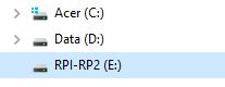
(a) The PICO appears as a new drive on the PC.
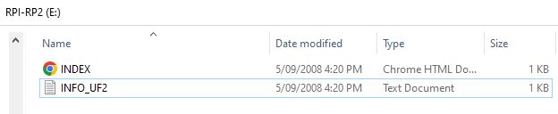
(b) The RPI-RP2 drive can be inspected - the Polarimeter.uf2 file will be copied here.
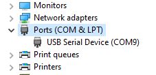
(c) In Device Manager, the PICO will appear connected as a USB Serial Device. Enter the COM port number seen here on the top line of C:\PicoPol\comport.txt. In this case the number entered on the top line would be a 9.
Step 2 : Installing the LabVIEWTM Runtime Executable
LabVIEWTM is a powerful graphical programming language developed by National Instruments. It has emerged as a widely used proprietary standard for instrument data acquisition and control.
Graphical user interfaces (GUI's) developed using LabVIEWTM are distributed as run-time executables, or RTE's. RTE’s are an extremely attractive concept, since an instrument's GUI can be made available to an end-user at no cost. For use in schools and undergraduate teaching labs with large class sizes this is a major benefit in putting low cost instrumentation in front of students.
Follow this procedure next :
1) To prepare your PC to use the polarimeter RTE (Polarimeter.exe), first run the NI run-time installer found in C:\PicoPol\LV_RTE.
2) Then run the NI-VISA runtime installer (also in C:\PicoPol\LV_RTE). NI-VISA is needed to provide support for the serial communications that are used to transfer data between the instrument and your PC.
Further information and technical support for LabVIEWTM is available at https://www.ni.com/en-au/shop/labview.html.
3) Inside C:\PicoPol\LV_RTE you will see a sub-folder called PolarimeterRTE. This folder contains Polarimeter.exe (the runtime executable used to control the polarimeter) and some supporting files. Do not move any of the files in the PolarimeterRTE sub-folder as they must all be present for the .exe to work correctly.
Instructions for using Polarimeter.exe are described in the next section.
Step 3 : Data Logging Using LabVIEW
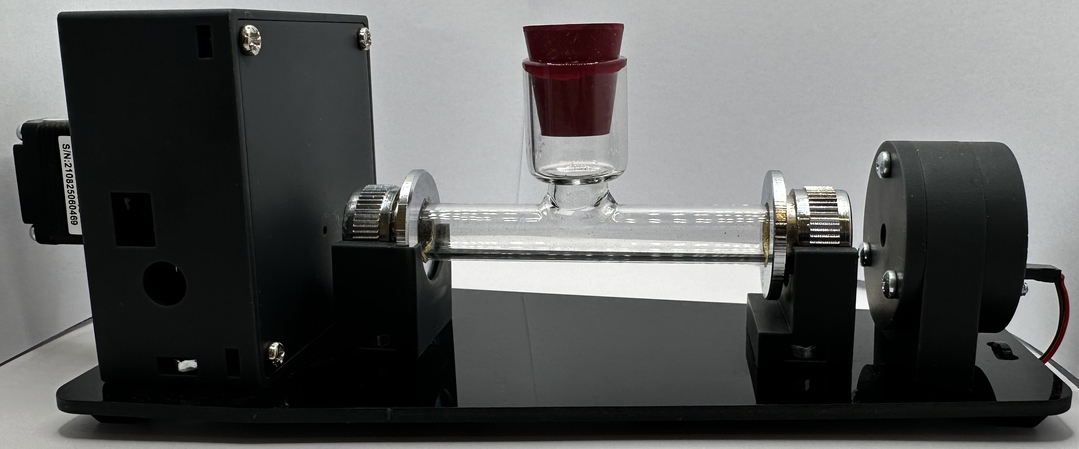
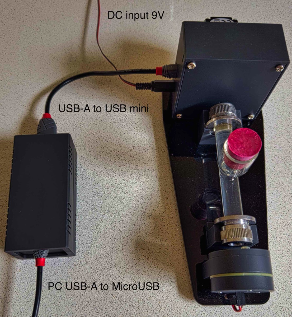
The PC interface needs to be connected as shown in the photo below. The connections here are : (i) a USB-A to USB-mini B cable connects between the PicoPol-PC and the polarimeter head, (ii) a micro-USB cable is connected from your PC to the PicoPol-PC and (iii) the 9V plug-pack powers the polarimeter head.
After making these connections check that the PICO appears as a COM port in Device Manager (with # as you saved in comport.txt). Then, double click on Polarimeter.exe - whose full path will now be C:\PicoPol\LV_RTE\PolarimeterRTE\Polarimeter.exe. After a short delay the polarimeter's LabVIEWTM screen will open. On startup the RTE will look for the comport.txt file to load in the COM port number of your instrument.
In the upper left corner of this screen you will see a forward arrow button that runs the executable when clicked. The forward arrow can now be pressed - a dialog will first appear offering you the option of file saving - make your selection, then click ok and optical rotation vs. time data will then be acquired. More information about the various controls and displays on screen can be found below.
When no further data acquisitions are required, press the stop button - the forward arrow button will then change from black to clear and the stepper motor will be stopped. A new run can then be initiated by repeating the above procedure.
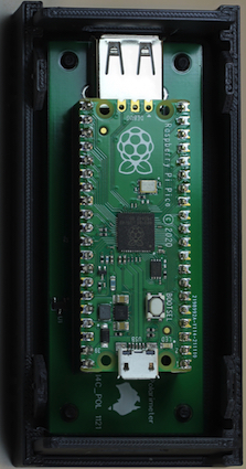
The lowest cost option for controlling the polarimeter is by using the small interface box shown at left. In this configuration a USB-A to USB-mini cable connects between the PCB shown in the left image and the detector end of the polarimeter, with the detector then powered directly by a 9V plug-pack. The PICO is connected to a USB port on the PC via a micro-USB cable.
The photo on the right shows these connections.
The photo on the right shows these connections.
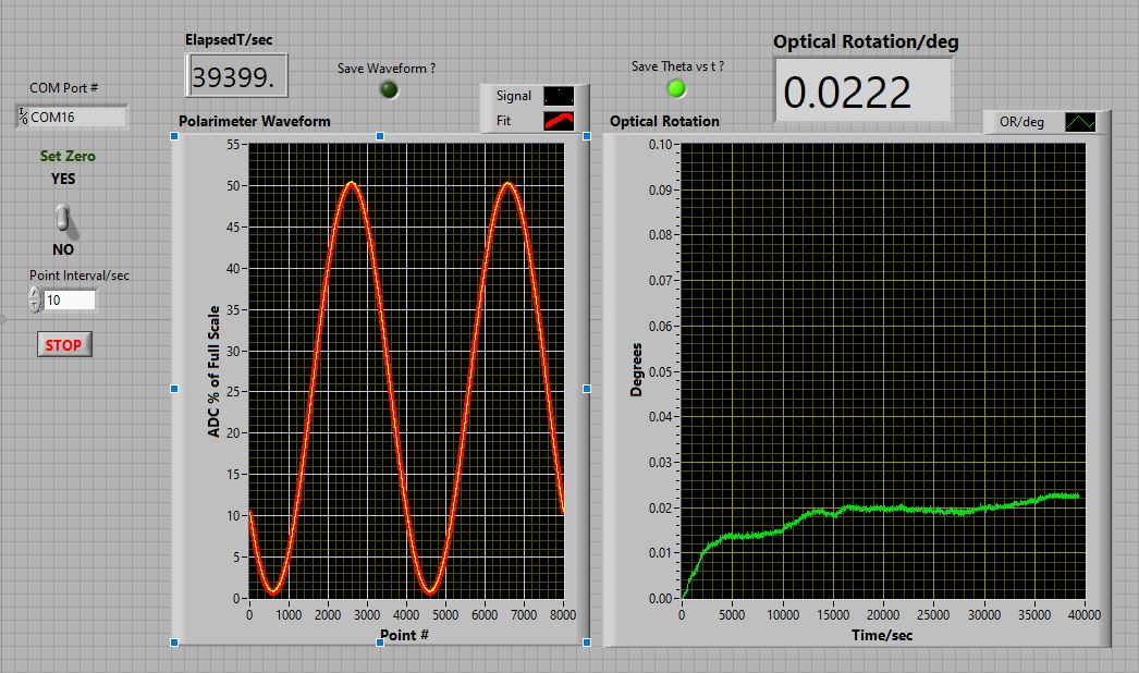
The control screen of the PicoPol-PC LabVIEW
Step 4 : Using the LabVIEW Control Panel
Here is a brief description of the various controls and indicators when using the runtime executable Polarimeter.exe, shown in the image above.
Once open, the RTE is launched by clicking the forward arrow button (just below the Edit menu). A dialog box then appears asking the user whether file saving is required. If so, there are two options selected by check boxes - the optical rotation vs. time dataset, the polarimeter waveform, or both. If the latter option has been checked, the polarimeter waveform will be saved to file once the run has been terminated using the stop button (see below). Normally one would only save the optical rotation vs. time dataset.
The RTE connects to the polarimeter using the COM port # shown; this number is loaded from the comport.txt file in your C:\PicoPol folder setup earlier.
The Set Zero toggle switch allows you to zero the optical rotation when a blank is being measured. The indicator labelled Theta/Degrees will reflect this change after a couple of measurement cycles. Once zeroed, the Set Zero toggle switch should be set to the No position to allow measurements to be made.
Below this toggle switch, the Point Interval/sec control is used to insert a specified delay between each motor movement/optical rotation measurement. The default value of this parameter is 10 seconds. With this setting the acquisition sequence will be a 4.8 second motor movement, followed by a waveform upload and then a 10 second pause before this cycle repeats. While the user can change the Point Interval/sec parameter the default value is recommended to ensure that the stepper motor remains cool when during very long kinetic runs.
The two graphical displays show (a) at left, the most recent 8000 point waveform acquired in yellow, with a cosine squared fit overlaid in red and b) at right, the optical rotation readings vs. time since measurements started. The elapsed time indicator shows the current time, with each iteration taking approximately 4.8 seconds plus the Point Interval/sec value.
To end a run, press the red stop button and wait until the forward arrow key changes from black to white.
The PicoPol-OLED interface page has some very important notes for getting the best results when operating the polarimeter - be sure to also read and understand these before using the instrument. In particular, if doing long kinetic runs the Delay parameter should be set to 10 seconds (or greater) to reduce the amount of motor heating during the experiment.