3D Printed Enclosures - Source, Detector and Controller
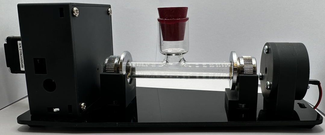
All enclosure and mechanical components for the PicoPOL system are supplied as precision 3D-printed parts, forming both the optical bench and the controller housing (for either the –PC or –OLED configuration).
These components are manufactured by a commercial 3D-printing service to ensure consistent dimensional accuracy and reliable fit. This is important for maintaining correct optical alignment and overall mechanical stability of the instrument.
In contrast to self-printed parts—where variations in printer calibration, material shrinkage, and layer adhesion can lead to fit and alignment issues—the supplied components have been produced under controlled conditions to provide predictable and repeatable assembly.
For transparency, the STL design files are made available here so that users can view the enclosure structure and understand how the instrument is constructed. However, there is no requirement to source or print these parts—the supplied components are ready to use as pre-built source, detector, and controller modules.
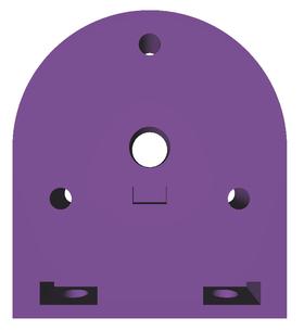
The PicoPol Detector Housing
DetectorA.stl
DetectorB.stl
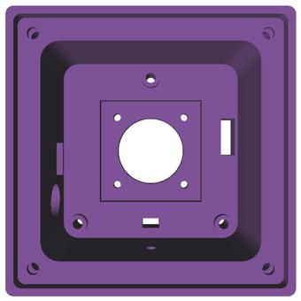
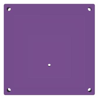
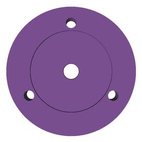
Located at either end of the polarimeter optical bench are the source and detector housings. The detector housing (DetectorA.stl) is a 3D-printed block that accomodates the detector PCB, and a rear-mounted stepper motor (to whose spindle a polarizer disk is attached). A 3D-printed cover plate (DetectorB.stl) mounts onto the front of the detector housing and provides optical access for the plane polarised input beam.
The PIcoPol Source Housing
The source housing is a sandwich consisting of three 3D-printed parts plus the source PCB. SourceA.stl has a recess into which a small fixed polarizer disk fits snugly. SourceA.stl mounts in front of SourceB.stl - and behind this sits the source PCB. The 5 mm LED on the source PCB protrudes through the central hole in SourceB.stl and faces forward towards SourceA.stl. The sandwich is completed by SourceC.stl with two cutouts giving access for a 2-pin power connector and to an intensity adjustment trimpot. The sandwich is held together by 3x25 mm M3 screws. Two slots in the SourceB.stl part allow mounting to the laser cut baseplate via M4 screws and captured nuts.
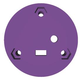
SourceA.stl
SourceB.stl
SourceC.stl
Polarimeter Cell Cradles and Cover

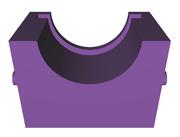

Cradle1.stl
Cradle2.stl
CellCover.stl
The polarimeter cell sits on two cradles that mount via M4 screws and captured nuts onto the polarimeter's laser cut acrylic baseplate, between the source and detector housings. Note that these cradles have small guide posts on either side.
When the cell cover (see the right image) is placed over the seated cell the guide slots in the cover slide over the guide posts on the cradles. The cell's entry port and stopper then pass through the central hole in the cover.
When the cell cover (see the right image) is placed over the seated cell the guide slots in the cover slide over the guide posts on the cradles. The cell's entry port and stopper then pass through the central hole in the cover.
The PicoPol-OLED Enclosure
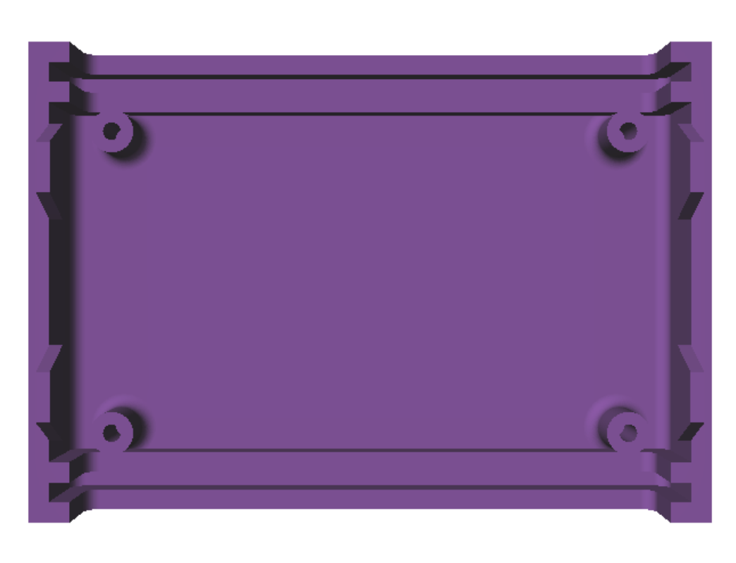


PicoPol-OLED_Bottom.stl
PicoPol-OLED_Top.stl
PicoPol-OLED_Front.stl
PicoPol-OLED_Back.stl
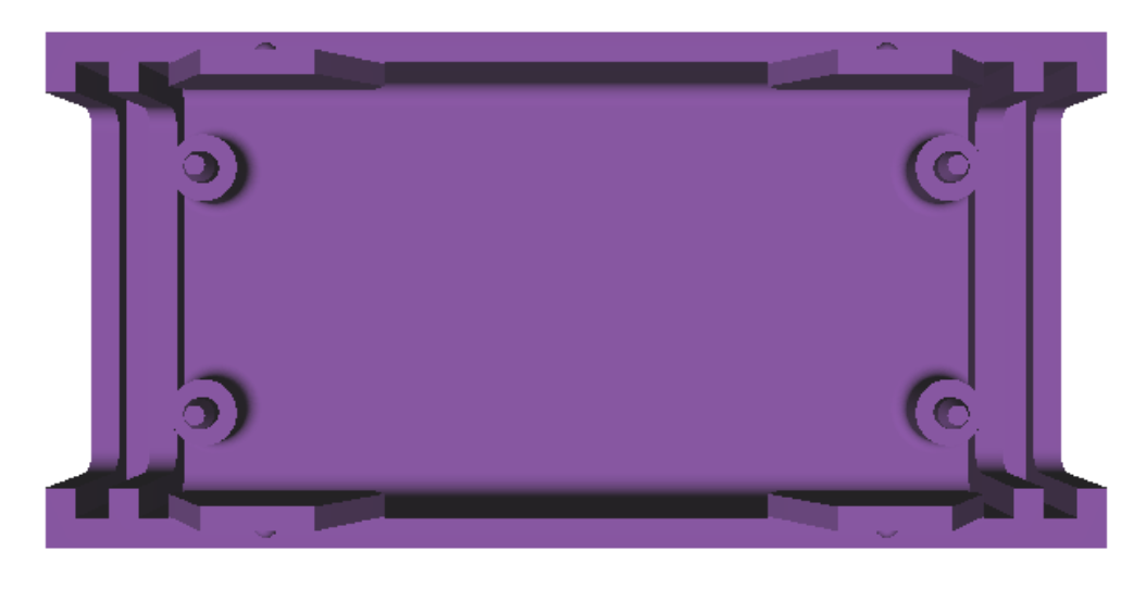
These images show the enclosure parts that house the PICO-OLED interface. The front and back panels fit into slots in the top and bottom panels. The PCB is secured via screws into the four posts in the bottom panel, while the top panel has a cutout allowing clearance for the OLED panel.
The PicoPol-PC Enclosure


PicoPol-PC_Bottom.stl
PicoPol-PC_Top.stl
PicoPol-PC_Front.stl
PicoPol-PC_Back.stl
These images show the enclosure parts housing the PicoPol-PC interface. The front and back panels fit into slots in the top and bottom panels. The front panel has a cutout for the micro-USB cable that connects the interface to the PC. The back panel cutout provides access for the USB-A to mini-USB cable that connects the interface to the detector housing on the polarimeter's optical bench.
Viewing the Enclosure Designs (.STL files)
For those interested in the mechanical design, the PicoPOL enclosure files are available as .stl files.
These can be viewed directly in your browser using a free online viewer such as https://viewstl.com
This allows you to rotate, zoom, and explore the full 3D structure of the optical bench and controller enclosure .stl's without installing any software.
There is no requirement to download or use these files—the supplied instrument already includes professionally manufactured 3D-printed components ready for use.