Checklist for the PicoPol-OLED
The PicoPol-OLED version (see here for ordering information) consists of the following items :
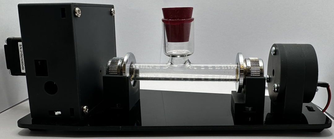
To assemble the PicoPOL optical bench -:
• Source and detector modules - the source fitted with a yellow (590 nm) LED
• a laser cut optical bench baseplate and 4 mounting feet
• 1 x 10 cm polarimeter cell
• A 2-wire cable to power the source PCB from the detector PCB
• all necessary mounting hardware (screws, nuts and washers)
To connect the -OLED controller -:
• A PicoPol-OLED controller module (PICO has been pre-programmed)
• an IR remote control with coin cell battery
• A USB-A to mini-USB cable
• A two-wire ribbon cable to 2.5 mm DC power plug
You will need to obtain a plug pack to power your instrument (this is not included to accomodate regional mains standards).
Power Requirements are as follows:
Regulated 9 V DC power supply, minimum 1 A current rating.
Connector: 2.5 mm inner diameter DC barrel plug, tip positive, metal barrel length ≥12 mm. Shorter plugs may not engage reliably.
Plug packs are readily available worldwide to accomodate these requirements but if in any doubt, please contact us beforehand at PicoPol@Instruments4Chem.com.
Once you have all of the necessary 3D-printed parts to hand, follow the detailed assembly instructions provided in the kit to build your polarimeter. The assembly process typically takes no more than an hour.
Initial Setup
The RPi PICO in the OLED controller has been pre-programmed so that the polarimeter can be used immediately. Begin by connecting the OLED controller to the polarimeter optical bench as shown in the photo below. From left to right at the rear of the OLED controller here is a list of the connections that need to be made -:
(I) The two wire ribbon cable connects to the power-in plug on the polarimeter head. At the OLED controller end, ensure the red wire is on the left and the brown wire is on the right (as seen from the front).
(ii) Immediately to the right of the two wire ribbon cable, plug in the USB-A end of the USB-A to mini-USB cable. The mini-USB end of this cable then connects to the polarimeter head as seen below.
(iii) Finally, connect the plugpack (far right hand side of the OLED controller as seen from the front) and apply power to the polarimeter.
The PICO in the OLED controller has a micro-USB connector allowing connection to your PC. This connection does not need to be made in stand-alone operation and would only be required should you ever need to perform a firmware upgrade (with assistance from I4C).
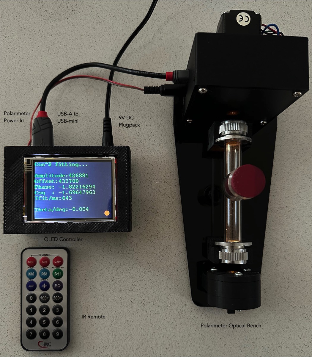
The setup for stand-alone polarimetric measurements with the PicoPol polarimeter, using the -OLED interface, showing the optical bench, OLED controller, IR remote and connecting cables. The yellow source light (peak wavelength near 590 nm) is weakly visible near the windows at each end of the polarimeter cell.
When using the IR remote, it is pointed at the small window in the enclosure - the image above shows the approximate position for doing so.
A cover (not shown in this image) can also be placed over the polarimeter cell if desired.
Central to the operation of the polarimeter is a stepper motor that spins the analysing polarizer at a constant rate. The RPi PICO in the -OLED interface controls this motor while simultaneously taking readings of the light intensity falling on a detector. On power-up the stepper motor is disabled.
The motor state can be toggled on/off using the “CH” key on the IR remote. When the motor is disabled, “Motor off” will be displayed at the bottom of the screen in red; when enabled this changes to “Motor on” in green.
n.b. The controller will only respond to key presses on the IR remote when a small filled (red/yellow) circle appears at the bottom of screen. Experiment using the “CH” key to get the feel of this operation. You will notice that while the OLED screen will indicate immediately when the motor state has been successfully toggled; the actual motor response will be slightly delayed. Once you are comfortable with using the IR remote, leave the instrument with the motor on.
Using the IR Remote Keypad
At any stage during the following operations, pressing the “9” key on the remote will bring up the menu options screen. Below is a list of the different operating modes of the instrument :
Remote “0” : The polarimeter can be placed into either “Set zero” mode, or “Measure” mode. The “0” key is used to toggle between these modes. The Set zero mode is used to set the optical rotation to 0.0000 when a blank is placed in the cell carrier for measurement. Once this has been done the instrument can be switched back to Measure mode to measure optical rotation values for samples. When in the menu option screen ("9") a red or green text field indicates whichever of these modes is currently active.
Remote “1” : Displays the fit parameters for the last recorded polarimeter waveform. If these parameters are displayed in red, the instrument is in Set zero mode; if the parameters are displayed in green, the instrument is in Measure mode. (Use the “0” key to toggle between these modes – see above)
Remote “2” : Displays the most recently measured 8000 point polarimeter waveform (a cosine squared function). Viewing the polarimeter waveform is essential when setting the light intensity produced by the LED source - this adjustment is carried out with a blank solution in-place as explained shortly.
Remote “3” : Shows a display having just the current optical rotation reading in degrees and the time in seconds since turn on.
Remote “4” : Resets the timer to zero.
Remote “9” : Brings up the list of menu options.
Remote “CH” : Toggles the stepper motor on/off. Text at the bottom of the screen indicates the motor status OFF/ON.
Remote “+/-“ : The delay between waveform acquisitions can be increased/decreased (in five second increments) using these two remote keys. The currently set value of the Delay parameter is displayed on the bottom line of the menu options screen. If doing a very long run (several hours) the stepper motor body will gradually warm up and this parameter can be used to reduce this warming as the motor will then be paused and disabled between measurements. This parameter can be set to either 5 or 10 seconds.
Remote “EQ“ : Puts the instrument into continuous acquisition mode, restoring the delay parameter to zero.
The OLED display uses the colours red and green to indicate modality - that is, to indicate whether a function is inactive or active. This applies to the motor state (off/on) and the Measurement mode. The fit parameters screen also follows this convention - displaying data in red if the instrument is currently in zero set mode, and green if in measuring mode.
Getting Started - Basic Operations
When making measurements ensure there is no interference to the light path, bearing in mind these very important points :
• The windows on the sample cell must be scrupulously clean – no fingerprints, liquids, dust, etc.
• The polarimeter cell must be filled sufficiently so that the light is not passing through either a meniscus or air.
• The cell must not be overfilled or liquids spilled on the instrument.
Your instrument will deliver very good performance providing careful attention is paid to all the above points. The critical thing here is that light is correctly entering the detector housing. If not, the quality of your measurements will be compromised.
Important Operating Notes :
1. On power-up it is normal for the LED intensity to decrease slightly as the LED die warms up. Leave the instrument powered up (motor can be inactive) for 15 minutes or so before adjusting the light intensity (see step (i) below) and making measurements - after that time the intensity will have stabilised.
2. For the most accurate measurements be sure to maintain exactly the same cell orientation for each measurement. This means the cell should always be upright and with the same end window facing the detector housing. With the inexpensive cell supplied with the instrument, small changes in optical rotation can be expected if either (a) the cell is rotated in position or (b) it is reinserted into the mounting cradles at 1800.
3. Ambient light will result in a very small increase in the baseline of the measured optical signal when compared with operation in a darkened room - but this will have minimal effect on the optical rotation readings unless the ambient light level is changing significantly. For best performance, operate the instrument in a location where the ambient light level is fairly constant. The instrument can be operated without a cover over the polarimeter cell , but use of the cover (provided) is recommended to achieve optical rotation readings that are stable to within 0.020.
4. The PicoPol uses a stepper motor to spin the analyser disk. Prolonged operation of the instrument will result in the motor body heating up - so the motor should be turned off (CH keypress on the remote) as soon as your measurements are finished. The delay parameter (+/- key) can also be used to insert a pause between motor movements to reduce motor temperature rise during operation. Using a delay setting of 5 or 10 seconds (instead of running the polarimeter in continuous mode - delay = 0) will ensure it can run for many hours without any thermal issues.
To gain familiarity with the remote controller and the various menu options, the following procedure is carried out with the polarimeter cell filled with water, stoppered and mounted in position on the cell cradles.
(i) Adjusting the Light Intensity
The polarimeter has a yellow LED installed in the source end of the instrument. With the cell in-place and the stepper motor running, click “2” on the remote to enable viewing of the optical signal registered by the detector. The signal range is a 12 bit number (0-4095) – with 0 corresponding to dark and 4095 light (and full scale). Ideally, the peak intensity in this cosine squared waveform when a blank is inserted should be between 80-90% of full scale – i.e. a peak reading between 3200 and 3600. This adjustment is done after the 15 minute warm-up period.
If the waveform appears “flat-topped” the LED intensity needs to be reduced. If however the waveform peak reading is less than 3200, the LED intensity needs to be increased. Ensuring the peak intensity is between 80-90% of full scale will ensure optimum performance - giving the most accurate optical rotation readings.
There is a small trimpot on the source PCB that can be adjusted with a jeweller’s screwdriver from the rear of the source housing to brighten/darken the LED’s output in order to set the intensity within this optimum range. The trimpot has a small screw/slot into which the screwdriver engages to make this adjustment but this is quite difficult to see and you may need to illuminate the opening with a torch/flashlight to see the slot to facilitate this operation. When making the adjustment, turning the screw anti-clockwise will lower the intensity, while turning clockwise will increase it.
Once this has been done for your blank, this adjustment should not require further changes.
(ii) Checking/Setting Zero Optical Rotation
With the polarimeter cell containing a blank solution still in-place, the instrument will have automatically set the optical rotation to 0.0000. To check this, press “1” on the remote keypad. On power-up the instrument will have entered Set zero mode. When in this mode the fit parameters on the OLED screen will appear in red and the optical rotation should read close to zero degrees. It can take a few measurement cycles (~10 seconds) for zeroing to take place after the blank has been inserted. Monitor Theta/deg at the bottom of screen for a few measurement cycles - it should fluctuate by less than 0.010.
If this display is green you must have already pressed the “0” key and the instrument has switched into Measurement mode – if so, press the “0” key again to revert back to the Zero-Set mode and then wait until optical rotation readings are zero degrees for your blank.
(iii) Making Measurements on Your Samples
Once the instrument has been zeroed you can proceed to take readings on your samples. Press the “0” key to enter Measurement Mode so that the fit parameters are displayed in green. Samples can then be measured as required. Readings can be noted down from either the fit parameters screen (remote “1”) or alternatively by viewing the simplified result screen (remote “3”) - the latter just displays the optical rotation reading and the time.
If you are attempting to measure optically dark samples that absorb strongly at the source wavelength, the amplitude of measured waveforms will be greatly reduced and the optical rotation readings will be less reliable. If you observe large fluctuations in the reported optical rotation readings this is an indication that the fitting algorithms are struggling due to low signal intensity.
As noted earlier, if the ambient light level is stable the polarimeter can be operated without placing the cover over the cell, but if this is not the case, use of the cover will give better stability of readings.
You will find that sugar (sucrose) solution(s) are very convenient and useful for initial testing of the instrument during the familiarisation process.