PicoPol-PC Setup and Requirements
This page explains how to operate a PicoPol-PC polarimeter. It assumes that you have already assembled the optical bench - see the Optical Bench page if you have not already done this.
The instructions provided on this page are a shortened version of material contained in the PicoPOL-PC User Manual - here the intention is to explain/summarize the workflow. A .pdf version of this manual can be downloaded using the button below.
The instructions provided on this page are a shortened version of material contained in the PicoPOL-PC User Manual - here the intention is to explain/summarize the workflow. A .pdf version of this manual can be downloaded using the button below.
In addition to the optical bench components the PicoPOL-PC option also includes -
• The PicoPol-PC controller and 3D-printed enclosure
• A USB-A to mini-USB cable
• A USB-A to micro-USB cable to connect your PC to the PicoPOL-PC controller PCB
• A Validation Module and cable for software verification and instrument familiarisation
You will need to obtain a plug pack to power your instrument (this is not included to accomodate regional mains standards).
Power requirements are as follows:
Regulated 9 V DC power supply, minimum 1 A current rating.
Connector: 2.5 mm inner diameter DC barrel plug, tip positive, metal barrel length ≥12 mm. Shorter plugs will not engage reliably.
Before connecting power to the polarimeter optical bench please use a multimeter to check the plug pack's voltage output and ensure that it close to 9V.
If in any doubt about these requirements please contact us beforehand at PicoPol@Instruments4Chem.com.
PicoPOL-PC Software Setup and Connection Summary
The Raspberry Pi Pico in the PicoPOL-PC controller is supplied pre-programmed. Firmware installation is not normally required, but can be performed if needed for updates or recovery.
Interaction with the instrument is via a supplied LabVIEW™ runtime executable. LabVIEW™ (developed by National Instruments) is widely used for instrument control and data acquisition. The PicoPOL-PC graphical interface is provided as a standalone runtime application, so no LabVIEW licence is required.
To operate PicoPOL-PC, a 64-bit Windows 11 PC is required. A LabVIEW 2025 runtime environment must also be installed; we provide an installer that includes all required components, including NI-VISA for communication with the instrument.
Once the runtime environment is installed and the controller is connected via USB, the PicoPOL-PC is automatically recognised by the PC as a serial (COM) port. The software then connects to the instrument without any manual configuration.
Before connecting a polarimeter, a Validation Module that is included in the package will first be used to fully check your software installation. In addition to this important function, the Module allows users to gain familiarity with all aspects of the instrument control software - the next section provides full details.
Initial Software Test Using the Validation Module
PicoPOL-PC is supplied with a XIAO RP2040-based Validation Module that allows the LabVIEW Runtime Engine, VISA drivers and USB communication to be tested before connecting the actual instrument.
The Validation Module generates synthetic waveform data that exercises the complete PicoPOL-PC acquisition and waveform fitting system. This allows verification that the software environment is functioning correctly prior to making measurements.
1. Run the LabVIEW runtime installer.
This may take several minutes and will typically require a PC restart.
2. Connect the Validation Module to your PC using the supplied USB cable.
For this test, leave the optical bench disconnected. Here we are only verifying communication between the PC and the Validation Module.
3. Open Device Manager and check under Ports (COM & LPT).
The Validation Module should appear as a USB Serial Device (COMx).
4. Run PicoPOL-PC.exe.
The LabVIEW control screen will open.
• Click the forward arrow (Run) button (top left)
• The button will turn black as the program starts
• The Connected? indicator should turn green and the COM port will enumerate as ASRLx::INSTR (COMx in Device Manager)
A dialog will appear offering file saving — for now, simply click OK.
After a short delay (~10 seconds), data will appear in the graph window.
Expected result
The Validation Module generates simulated PicoPOL data internally.
Typical displayed results are:
• approximately 0.00° in blank mode
• a fixed non-zero optical rotation in simulated sample mode
Small fluctuations in the respective readings are normal and intentionally included in the generated data.
Successful operation confirms that:
• the LabVIEW Runtime Engine is functioning correctly
• VISA communication is working
• USB serial communication is operating correctly
• Waveform acquisition and fitting are functioning correctly
Stopping the test
• Click the red STOP button
• Wait briefly for the application to close
• The Run arrow will return to white
Troubleshooting
If the Connected? indicator remains red:
• Check that the Validation Module appears as a COM port in Device Manager
• Check that the USB cable is securely connected
Once Validation Mode has operated successfully it should be disconnected.
✅ You are now ready to take measurements — see the next section.
Connecting PicoPOL to Take Measurements
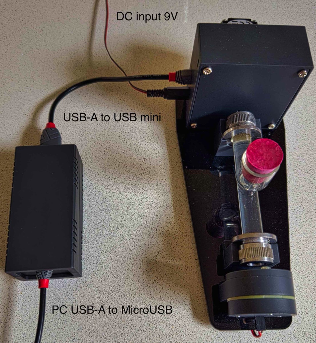
Connect the system as shown in the photo below. Three connections are required:
1. A USB-A to mini-USB cable between the PicoPOL-PC controller and the polarimeter head
2. A micro-USB cable from your PC to the PicoPOL-PC controller
⚠️ Note: Micro-USB connectors are fragile—avoid excessive force when connecting to the RPi PICO board.
3. A 9 V power supply (2.5 mm barrel connector) to the detector module. Important : power should always be off while making connections.
Power-up check
After checking your connections, switch on the 9V supply (ensure the correct voltage has been confirmed).
Check that the source module is powered:
Glow from a small red LED should be visible at the rear of the source module
A yellow light beam should emerge from the front of the source module and illuminate the detector module
This illumination should form a well centred yellow patch over the small optical access hole in the detector cover. Use a piece of white paper or card to check this. If the beam is off-centre you must reposition the two modules on the baseplate.
Running the instrument
Double-click PicoPOL-PC.exe
After a short delay, the LabVIEW™ control screen will open
Click the forward arrow (Run) button
After a brief delay:
The stepper motor will begin rotating
A sinusoidal waveform will appear on the screen
Stopping and restarting
Press the STOP button to end a run
The Run arrow will return to its clear state and the motor will stop
A new run can be started at any time by pressing the Run button again
⚠️ Important: Always use the on-screen STOP button to end a run.
Do not use the LabVIEW “Abort” button (top toolbar), as this may leave the communication port open or the instrument in an undefined state.
Further details of the on-screen controls and displays are provided below.
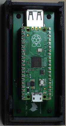
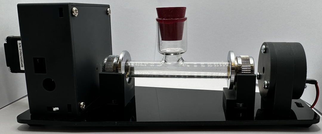
The PicoPOL-PC option controls the polarimeter using the small interface box shown at left. In this configuration a USB-A to USB-mini cable connects between the PCB shown in the left image and the detector end of the polarimeter, with the detector then powered directly by a 9V plug-pack. The PICO is connected to a USB port on the PC via a micro-USB cable.
The photo on the right shows these connections.
The photo on the right shows these connections.
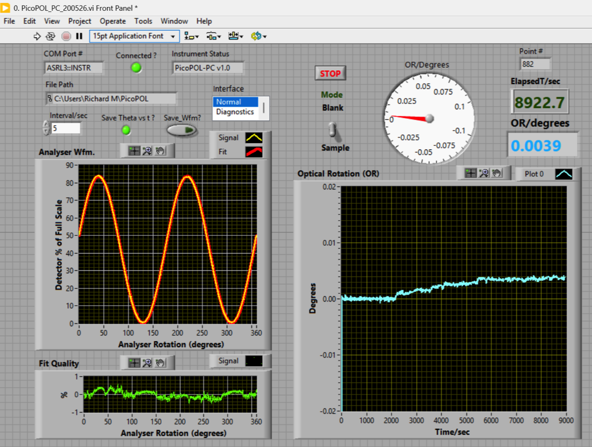
The control screen of the PicoPol-PC LabVIEW
PicoPOL-PC Interface: Controls and Operation
Starting a Run
Once opened, the Run-Time Executable (RTE) is started by clicking the forward arrow button (just below the Edit menu). A dialog box then appears asking whether data should be saved.
Two options are available (via checkboxes):
Optical rotation vs. time dataset
Polarimeter waveform
Either or both may be selected. If waveform saving is enabled, the waveform will be written to file when the run is terminated using the stop button (see below). In most cases, only the optical rotation vs. time dataset needs to be saved.
Zeroing the Instrument
The Set Zero toggle switch is used to zero the optical rotation when a blank is in place. The Theta/Degrees indicator will reflect this change after a few measurement cycles.
Once zeroing is complete, return the switch to the No position to enable sample measurements.
The Set Zero toggle switch is used to zero the optical rotation when a blank is in place. The Theta/Degrees indicator will reflect this change after a few measurement cycles.
Once zeroing is complete, return the switch to the No position to enable sample measurements.
Point Interval (Delay Control)
The Point Interval/sec control sets the delay between successive measurements. The default value is 0 seconds - I.e. no delay after each motor rotation.
If the point interval is set to a non-zero, each measurement cycle then consists of:
- ~5 seconds motor rotation and data acquisition
- the waveform transfer to the PC
- a pause before the next cycle as set by the point interval
For long kinetic runs the stepper motor body will warm up if being run continuously. In this case it is recommended to set a point interval of 5-10 seconds. This will give a sufficiently regular measurement interval while also keeping the motor body cool.
Graphical Displays
Two graphs are displayed:
Left: Most recent 8000-point waveform (yellow) with cosine-squared fit (red)
Right: Optical rotation vs. elapsed time
The elapsed time indicator shows the total run time. Each measurement cycle takes approximately 5 seconds + Point Interval/sec.
Two graphs are displayed:
Left: Most recent 8000-point waveform (yellow) with cosine-squared fit (red)
Right: Optical rotation vs. elapsed time
The elapsed time indicator shows the total run time. Each measurement cycle takes approximately 5 seconds + Point Interval/sec.
Stopping a Run (Important)
To end a run, press the red stop button within the VI and wait until the forward arrow button changes from black to white.
Do not use the external red stop button next to the forward arrow.
Doing so prevents the COM port from closing correctly, and the controller may appear as not connected on the next run.
If this occurs, simply start the program again—the COM port should reconnect normally.
Important Notes
The OLED controller page contains important guidance for achieving the best performance. These recommendations also apply when using the PC interface and should be reviewed carefully.
In particular, for long kinetic runs, the Point Interval/sec parameter should be set to 5 seconds or greater to minimise stepper motor heating during extended operation.