PicoPOL Optical Bench Assembly
The PicoPOL optical bench consists of the following components-:
• Pre-assembled source and detector modules; the source fitted with a yellow (590 nm) LED
• 2 cell cradle support blocks
• a laser cut optical bench baseplate and 6 mounting feet
• 1 x 10 cm polarimeter cell
• A 2-wire cable to power the source PCB from the detector PCB
• all necessary mounting hardware (screws, nuts and washers)
In operation a cell cover (also supplied) can be placed over the cell to exclude external light.

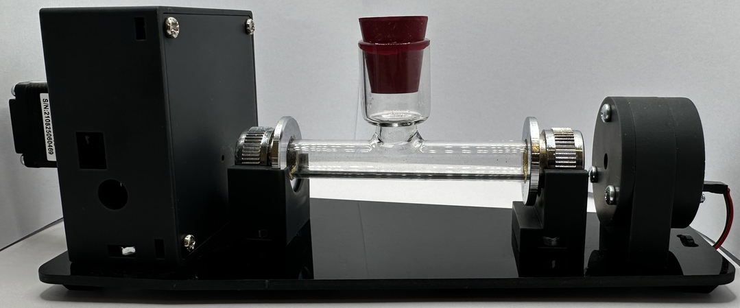
Begin by assembling the polarimeter optical bench, first mounting the detector module, then the source module and lastly the two cell carrier blocks securely onto the baseplate in the positions as shown in the image above. Mounting is achieved using the M4 screws, captured nuts and washers that are provided. The washers should be fitted under the screw heads on the underside of the baseplate.
Note - the carrier blocks need to be accurately positioned so that the cell will fit neatly into the slots when mounted. They need to be fitted with their vertical slots each facing toward the middle of the baseplate. Once the carrier blocks are in their correct positions the cell should be set aside for the time being to avoid risk of breakage.
During fitting of the above 4 components you may find that the captured nuts rotate as the screws are tightened. If so, cut off and then wedge a short length of cable tie (provided) into the captured nut slots to prevent the nut spinning - then tighten the screws - but don't over tighten.
To complete the optical bench assembly connect the custom two wire cable that runs between the 2 pin header at the rear of the detector module to the 2 pin header at the rear of the source module - this powers the LED in the source module.
That's it - the optical bench is now assembled !!