Using the PicoPol-OLED Polarimeter
This page explains how to operate a PicoPol-OLED polarimeter. It assumes that you have already assembled the optical bench - see the Optical Bench Assembly page for instructions.
In addition to the optical bench components the PicoPOL-OLED option also includes -
• A pre-programmed PicoPol-OLED controller module and 3D-printed enclosure
• an IR remote control with coin cell battery
• A USB-A to mini-USB cable
• A two-wire ribbon cable to 2.5 mm DC power plug
You will need to obtain a plugpack to power your instrument (this is not included to accomodate regional mains standards).
Power requirements are as follows:
Regulated 9 V DC power supply, minimum 1 A current rating.
Connector: 2.5 mm inner diameter DC barrel plug, tip positive, metal barrel length ≥12 mm. Shorter plugs will not engage reliably.
Before connecting power to the polarimeter optical bench please use a multimeter to check your plug pack's voltage and ensure that it outputs 9V.
If in any doubt about these requirements please contact us beforehand at PicoPol@Instruments4Chem.com.
Initial Setup
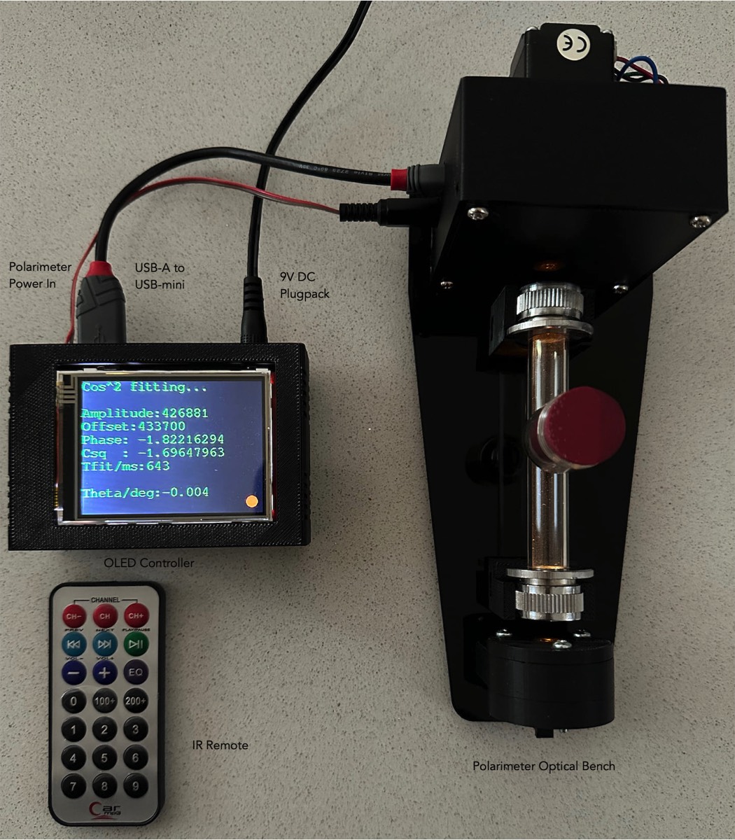
The RPi PICO in the OLED controller has been pre-programmed so that the polarimeter can be used immediately. Begin by connecting the OLED controller to the polarimeter optical bench as shown in the photo below. From left to right at the rear of the OLED controller, the required connections are:
(i) The two-wire ribbon cable connects to the power input on the detector module. At the OLED controller end, ensure the red wire is on the left and the brown wire is on the right (as viewed from the front).
(ii) Immediately to the right of the two-wire ribbon cable, connect the USB-A end of the USB-A to mini-USB cable. The mini-USB end of this cable then connects to the detector module, as shown below.
(iii) Finally, connect the plugpack (far right-hand side of the OLED controller, as viewed from the front) and apply power to the polarimeter.
The PICO in the OLED controller also includes a micro-USB connector for connection to a PC. This is not required for stand-alone operation and is only needed for firmware updates (with assistance from I4C).
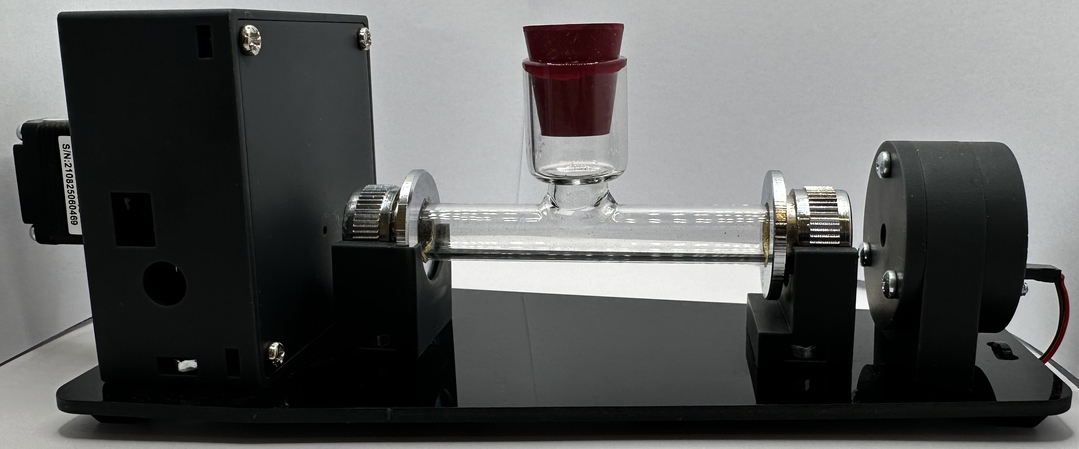
The setup for stand-alone polarimetric measurements with the PicoPol polarimeter, using the -OLED interface, showing the optical bench, OLED controller, IR remote and connecting cables. The yellow source light (peak wavelength near 590 nm) is weakly visible near the windows at each end of the polarimeter cell.
When using the IR remote, it is pointed at the small window in the enclosure - the image above shows the approximate position for doing so.
A cover (not shown in this image) can also be placed over the polarimeter cell if desired.
On power-up, a welcome screen is displayed for a few seconds, after which the display shows the control options accessible via the IR remote.
Central to the operation of the polarimeter is a stepper motor that rotates the analysing polarizer at a constant rate. The RPi PICO in the OLED controller drives this motor while simultaneously measuring the light intensity at the detector. On power-up, the stepper motor is disabled.
The motor state can be toggled on or off using the “CH” key on the IR remote. When the motor is disabled, “Motor off” is displayed at the bottom of the screen in red; when enabled, this changes to “Motor on” in green.
Note: The controller only responds to key presses when a small filled (red/yellow) circle appears at the bottom of the screen. Try using the “CH” key to become familiar with this behaviour. The display updates immediately when the motor state is toggled, but the motor itself responds with a slight delay. Once you are comfortable using the IR remote, leave the instrument with the motor on.
Using the IR Remote Keypad
The IR remote provides access to all operating modes of the instrument.
When a key is pressed on the IR remote, a unique sequence of timed optical pulses is emitted. This is decoded into an action by the onboard IR detector and the RPi PICO, both located within the PicoPOL-OLED controller. The entry point for this IR signal is a small rectangular cut-out at the lower left front of the enclosure. The remote must be pointed at this “window” to control the polarimeter.
At any stage during operation, pressing the “9” key will display the menu options screen. The available operating modes are listed below:
Remote “0” : Toggles between “Set zero” mode and “Measure” mode.
Set zero mode is used to define the optical rotation as 0.0000 with a blank solution in place. Once this has been completed, the instrument can be switched back to Measure mode for sample measurements. When viewing the menu screen (“9”), a red or green text field indicates the currently active mode.
Remote “1” : Displays the fit parameters for the most recent polarimeter waveform. Parameters are shown in red when the instrument is in Set zero mode, and in green when in Measure mode (use the “0” key to toggle between modes).
Remote “2” : Displays the most recently acquired 8000-point polarimeter waveform (a cosine-squared function). Viewing this waveform is important when setting the LED light intensity. This adjustment should be carried out using a blank solution, as described below.
Remote “3” : Displays the current optical rotation (in degrees) together with the elapsed time (in seconds) since power-up.
Remote “4” : Resets the timer to zero.
Remote “9” : Displays the menu options screen.
Remote “CH” : Toggles the stepper motor on or off. The motor status (OFF/ON) is indicated at the bottom of the screen.
Remote “+ / –” : Adjusts the delay between waveform acquisitions in 5-second increments. The current delay value is shown on the bottom line of the menu screen. For extended runs (several hours), the stepper motor will gradually warm up; introducing a delay reduces this heating by pausing and disabling the motor between measurements. The delay can be set to 5 or 10 seconds.
Remote “EQ” : Enables continuous acquisition mode and resets the delay parameter to zero.
The OLED display uses red and green to indicate operational state. In general, red denotes inactive and green denotes active. This convention applies to the motor state (OFF/ON), the measurement mode, and the fit parameters display (red for Set zero mode, green for Measure mode).
Instrument Setup, Operation and Measurement Guidelines
Important Operating Notes
1. LED warm-up
On power-up, the LED intensity will decrease slightly as the LED die warms. Allow the instrument to stabilise for approximately 15 minutes (the motor may remain off) before adjusting light intensity or making measurements.
2. Cell orientation
For best accuracy, maintain identical cell orientation for all measurements. The cell should always be upright, with the same end window facing the detector. With low-cost cells, small changes in optical rotation may occur if the cell is rotated or reinserted at 180°. Further guidance can be found below under "Sample Cells and Measurement Technique".
3. Ambient light
Ambient light introduces a small baseline offset but has minimal impact unless it changes significantly. For best performance, operate in a location with stable lighting conditions. While the instrument can be used without a cover, the supplied cover is recommended to achieve stability of ~0.02°.
4. Motor heating
The stepper motor will warm during extended operation. Turn the motor off (CH key) when measurements are complete. The delay parameter (+/– keys) can be used to reduce heating by pausing the motor between measurements. A delay of 5–10 seconds allows extended operation without thermal issues.
To become familiar with the instrument and remote operation, the following procedure should be carried out using a water-filled, stoppered cell mounted in position.
(i) Adjusting the Light Intensity
The instrument is fitted with a yellow LED source. With the cell in place and the motor running, press “2” on the remote to display the detector signal.
The signal is a 12-bit value (0–4095), where 0 represents darkness and 4095 full scale. Ideally, the peak of the cosine-squared waveform (with a blank) should lie between 80–90% of full scale (approximately 3200–3600). This adjustment should be made after the 15-minute warm-up period.
If the waveform appears flat-topped, the intensity is too high. If the peak is below ~3200, the intensity is too low. Maintaining the peak within this range ensures optimal accuracy.
A small trimpot on the source PCB allows adjustment of LED intensity. This can be accessed from the rear of the source housing using a jeweller’s screwdriver. The adjustment slot may be difficult to see and may require illumination. Turning the screw anti-clockwise reduces intensity; clockwise increases it.
Once set for the blank, further adjustment is rarely required.
(ii) Checking / Setting Zero Optical Rotation
With the blank solution still in place, the instrument will automatically set the optical rotation to 0.0000.
Press “1” to view the fit parameters. On power-up, the instrument is in Set zero mode, indicated by red text. The optical rotation should read close to zero. Allow a few measurement cycles (~10 seconds) for stabilisation; fluctuations should be less than ±0.01°.
If the display is green, the instrument is in Measurement mode. Press “0” to return to Set zero mode and wait until the reading stabilises at zero.
(iii) Measuring Samples
Once zeroing is complete, press “0” to enter Measurement mode (green display). Measurements can then be taken.
Results may be viewed either on the fit parameters screen (“1”) or on the simplified display (“3”), which shows only optical rotation and elapsed time.
For strongly absorbing samples, signal amplitude will be reduced and measurement reliability may decrease. Large fluctuations in optical rotation readings indicate insufficient signal for stable fitting.
As noted earlier, the instrument can operate without a cell cover under stable lighting conditions; however, use of the cover is recommended for best stability.
Sucrose solutions are convenient and reliable for initial testing and familiarisation.
(iv) Sample Cells and Measurement Technique
The precision and accuracy specifications quoted for PicoPOL refer to the instrument itself under stable operating conditions. In practice, the overall quality of a polarimetric measurement is influenced not only by the instrument but also by the optical cell and the consistency with which it is handled.
PicoPOL is designed to operate with economical glass sample cells that provide excellent value and are entirely suitable for educational, laboratory, and routine analytical applications. However, such cells are not manufactured to the same optical tolerances as high-end research-grade polarimeter tubes. Small variations in path length, window flatness, parallelism, and mounting geometry can therefore contribute additional measurement uncertainty.
One effect that users may observe is a dependence of the measured optical rotation on cell orientation. Rotating a cell by 180° can sometimes produce a measurable change in the reported rotation, occasionally approaching several tenths of a degree. This behaviour is generally caused by slight imperfections in the optical windows or by small wedge angles between the cell faces. These imperfections can introduce weak lensing effects that alter the optical path through the instrument. For the highest measurement consistency, the cell should therefore be inserted in the same orientation for both blank and sample measurements. Many users find it helpful to place a small orientation mark on the cell to ensure repeatable positioning.
Even when the cell remains in the same nominal orientation, small rotational or lateral shifts during insertion may produce minor changes in the blank reading. In typical use these effects are small, often on the order of a few hundredths of a degree, but they can become significant when attempting measurements near the instrument’s ultimate precision limit. Careful and repeatable placement of the cell is therefore recommended whenever high-accuracy work is being performed.
Another important consideration is the choice of blank. An air blank and a solvent-filled blank are not equivalent. Filling the cell with water or another solvent changes the refractive index distribution within the optical path and may introduce slight lensing or de-lensing effects arising from the cell windows and liquid interfaces. Consequently, the most accurate procedure is to record the blank using the same cell filled with the solvent that will be used for the sample. The sample measurement is then referenced directly against this solvent blank, ensuring that any optical effects associated with the cell and solvent are automatically compensated.
When these simple precautions are followed—using a consistent cell orientation, careful repositioning, and an appropriate solvent blank—the overall measurement performance can approach the precision and accuracy levels demonstrated during PicoPOL validation testing. In most cases, the remaining uncertainty is dominated by sample preparation and cell handling rather than by the instrument itself.